|
The reason for this circuit is simply that
standard Fieros do not come with a knock sensor provision. While
the TDC/DOHC ECUs DO have a knock provision, the Haltechs do
not. If you are running the Haltech, chances are pretty good
that you are turbocharging the motor, which means that knock
detection becomes even more critical for maximum performance and
to lessen the chances for engine failure due to detonation.
While this circuit is not active, meaning it will not adjust the
timing automatically, it WILL let you know that a timing
adjustment must be made.
Here's the schematic
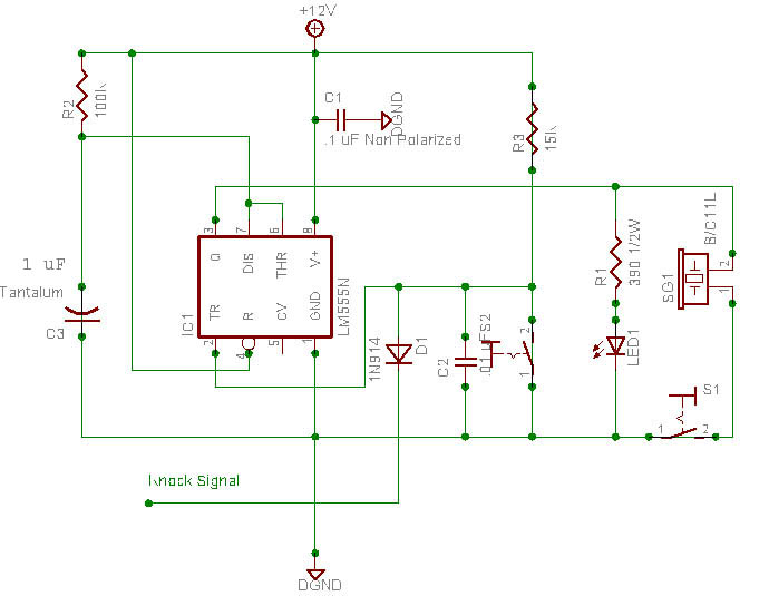
Parts List
Most of these parts can be located
at your local Radio Shack or can be ordered via online vendors
such as Mouser, Digikey, JameCo, etc...
Don't forget to pick up a
breadboard and project box to mount all of the components in.
Nice feature is that you can remotely mount the switches and the
LED indicator to your dash and hide the project box for that
stealth look. Try to keep all leads as short as possible.
Capacitors
| C1 |
.1uF Non Polarized Disc |
| C2 |
.01uF Non Polarized Disc |
| C3 |
1uF Tantalum |
Resistors
| R1 |
390 Ohm, 1/2 Watt, 5% |
| R2 |
100K Ohm, 1/4 Watt, 5% |
| R3 |
15K Ohm, 1/4 Watt, 5% |
IC
Diodes
Switches
| SW1 |
Alarm On/Off |
| SW2 |
Momentary Activation, Normally Open |
Piezo Buzzer
Be sure to take your time
when soldering to ensure that you have a good connection without
an excessive amount of solder. Also make sure that all
connections going to the Knock Sensor are soldered and heat
shrink protected for a good connection. The knock sensor should
be the standard GM type, but it's always wise to replace it
while the motor is out of the vehicle.
Author: 85frankenstein |