|
Many
of our readers may be switching from a 4 cylinder to the DOHC,
which would either necessitate purchasing a front V-6 mount from
the salvage yard or manufacturing a new one from scratch. Dave
Ellis AKA ltlfrari has been so kind as to provide the specs as
well as a detailed write-up and pictures on how to manufacture
the mount. The following is his write-up in full.
                This is my solution
                to mounting my 95 3.4 DOHC onto an 85 cradle with a 5 speed
                Isuzu transmission.


                I replaced the standard tranny and engine mounts with West Coast
                Fiero poly mounts. The tranny mounts are simple bolt up
                replacements for the existing mounts so I will not go into
                detail of those here.


                As I was replacing a 4 cylinder engine with the 3.4 I did not
                have an existing engine mounting plate that I could use. I had
                read on Pennock's that an 88 V6 mount would work but when I
                looked at how the end of the engine aligns above the (WCF)
                engine mount I could not see how the bracket would fit in my
                situation. This is not to say there is anything wrong with the
                WCF mount just that so far as I can see a standard engine
                mounting plate would not work.
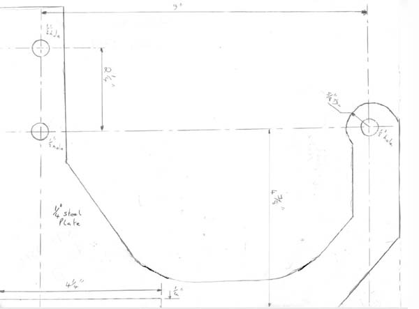
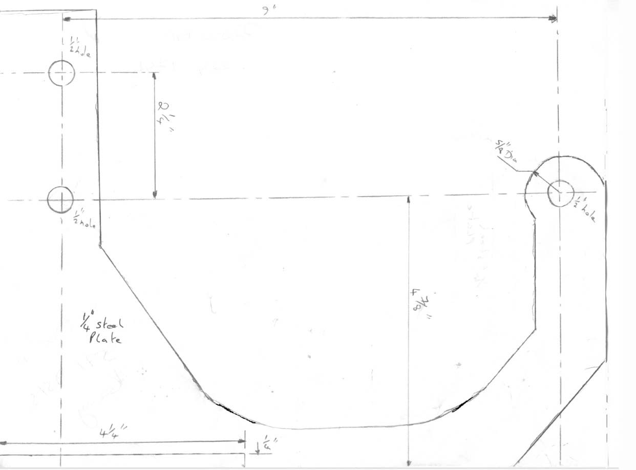
                Figure 1 shows the basic engine mounting bracket that I had made
                from 1/4 inch steel. I made some slight changes to the actual
                bracket from the drawing. In particular I decided that the
                cutout at the lower left of the bracket where the 'foot' goes
                made that corner of the bracket too narrow so the cutout is not
                only 2 1/4 inches long and I had the guy who made my bracket
                notch the foot to match so that they interlock together.

                The foot is simply a piece of 1/4 plate steel 4 1/4" x 2 1/2".
                Click picture for a larger version
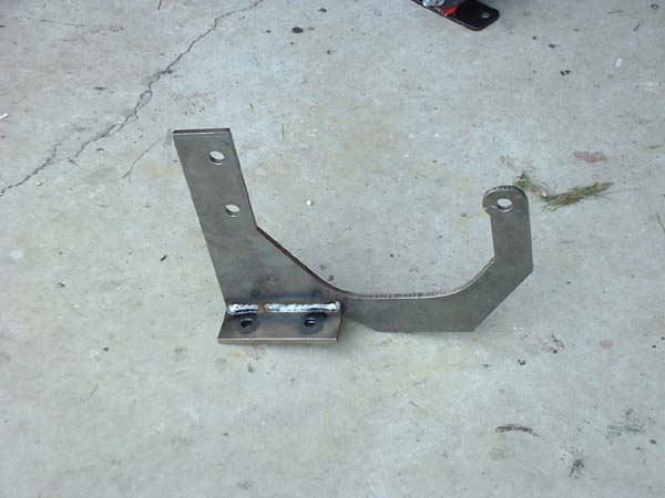
                Figure 2 shows the completed mount. To drill the holes in the
                foot I bolted the mount to the engine and installed the WCF
                mount and marked where I wanted the bolt holes to go,
                disassembled it and drilled the holes. I used the 3/8" bolts
                that came with the WCF mounts.
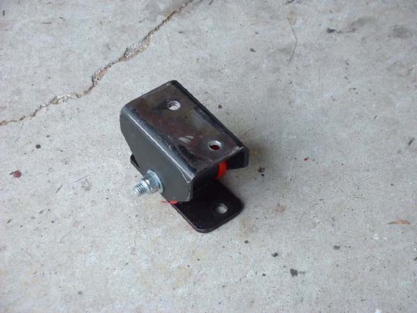
                Figure 3 shows the modifed WCF engine mount. Because the WCF
                mount already had holes drilled in it that did not align with
                the new holes in my bracket I had the existing holes welded up
                and ground flat. Then I bolted it all up again, marked where the
                holes in the foot matched the WCF bracket, removed everything
                and drilled new holes in the WCF part.
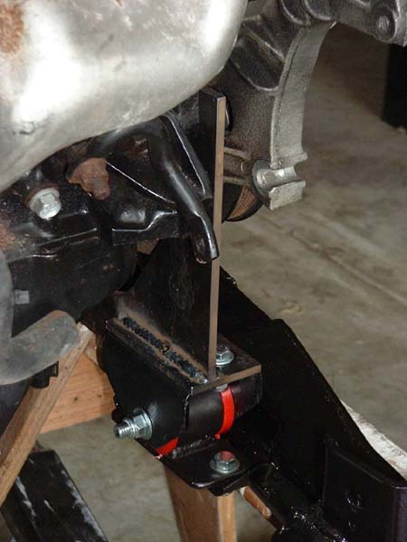
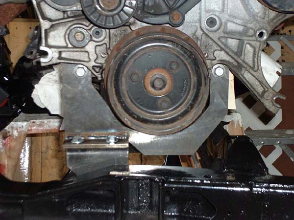
                Figure 4 and Figure 5 show the completed engine bracket in
                place.
Author: Dave Ellis AKA ltlfrari
|