|
Introduction
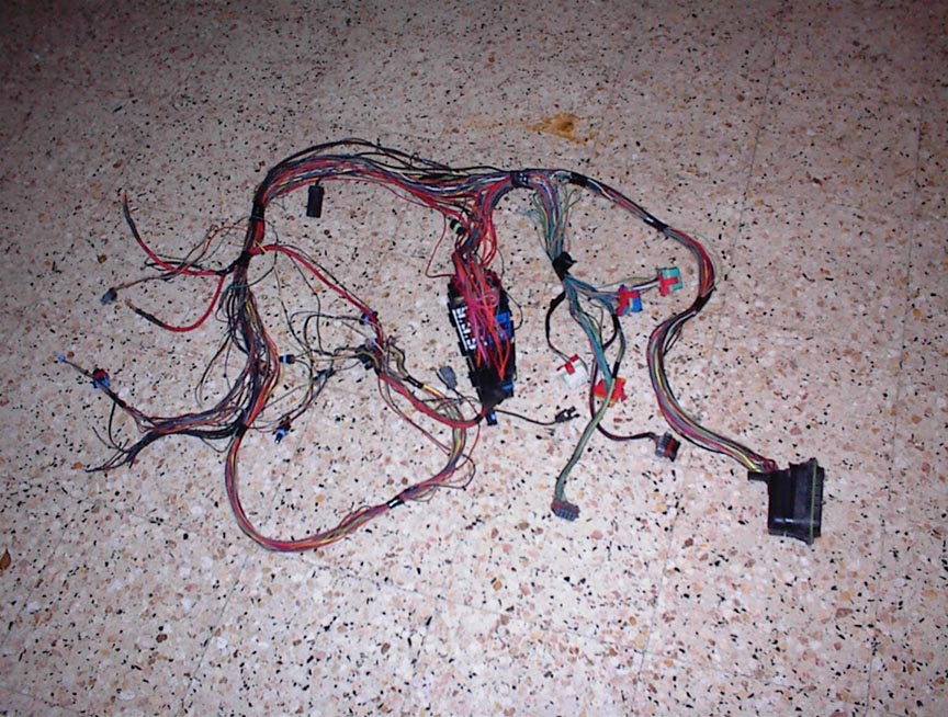
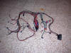
Here is the
cookie monster of the 3.4 DOHC swap, the electrical hell.
Well, there is no need to be scared or frustrated anymore
nor pay lots of money to a shop to get it done. Here in
DOHCFiero.com will show you how to do it. DOHCFiero or any
collaborator is NOT responsible for any damage of your
vehicle, do it at your own risk. Sorry but we have to cover
of our asses. ;)
There are 3
different types of electrical systems for the 3.4 DOHC 91-93
are MPFI, 94-95 SFI, 96-up are ODB II. For the Fiero swap
the best shot is the 91-93 harness and ECM. This "tutorial"
is based on the 91-93 harness and ECM, actually I use an
auto harness and manual ECM due my GT is 5 speed manual.
Also there are 2 different engine styles 91-95 and 96 up.
They differ in heads, intake, exhaust manifolds and the
location of the DIS. Different people do same things in
different ways, this maybe not the best way to do it but is
one of them, and is better than none.
Hands On
First you
have to consider if you will use an auto (not recommended)
or a manual tranny. This will determine how difficult will
be the process. Let me explain, if you have a manual harness
& ECM and your car is a manual then your swap will be more
easy going. It is preferable that you get the ECM, harness
and engine from the same car, this will make it easier for
harness distribution as I stated before auto or manual. But
if you are like some people (my self included) that buy
parts as they are available you may have a rough ride in the
harness. I have a 92 manual ECM, 91 auto harness with some
cut wires and a 96-up engine. I decided to use the 97 engine
due the improved heads, intake and exhaust, but that is
other story. Now, on with the process.
Grab the
schematics
here. Print them and look at all of them, you will need
to be familiarized with them to make sense of it all. Lets
move a little faster, the main mojo is in the 3.4 DOHC C100
connector, is the one that goes plugged into the firewall.
In the schematics you can see the pin outs with its
description, that is what we have to match and connects to
the Fiero C203 and C500 connectors. Don't get dizzy, the
hard work is done already, that's is what is page is all
about ;) . Now that you realize that is not that difficult
lets start the madness.
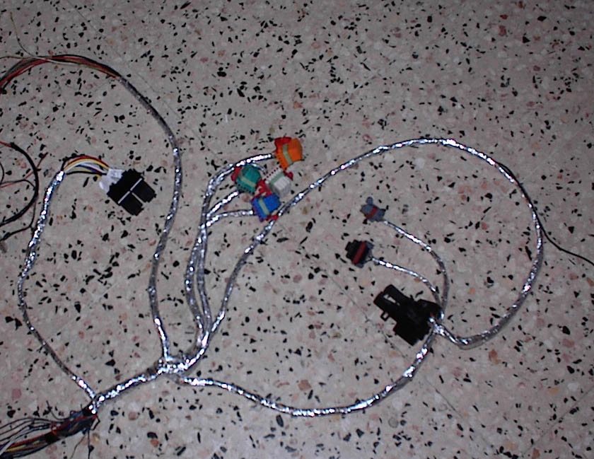
In the 3.4
DOHC harness are some cables that is not needed for the
Fiero, is recommendable to take them off-depends in your
config. In my case I cut some wires that is related with the
auto tranny, and some equipment that the Fiero don't have or
the circuit works in the remaining Fiero harness. The idea
of cut those wires is to create electrical troll that can
make your life a living hell!. LOL!! J/K Is for make the
harness more easy to work on and more simpler. But in order
to do so you will need to take the loom off; yes have to do
so; and clean the harness.
For the
ones that have to pass hell like me here is some preparation
info. The 96-up engine use the DIS next to the upper intake,
the 91-95 use the DIS below the front manifold. To use the
91-93 harness we have to move the DIS cables to the upper
intake side. That will be in the Fiero near the battery
location. To do this madness you have to take all the loom
off and tapes. BUT beware to attach again the cables when
moving the DIS ones to it new location, you don't want a
spaghetti in there. The best way to verify the proper
position is attach the harness to the engine while is out of
the car.
Now that
you have cut (not the plug, the idea is to remove the cables
as far as possible) and re-route your cables we can start
the cut and paste with the connectors. BTW, this is placing
the ECM in the firewall where the battery is located. You
can now move the battery to the front compartment, come on!!
You know you want that for a long time ;) . If you want to
place the ECM inside like the Fiero then you will have to
cut all ECM cables and do some extensions (I'm not 100% sure
but when I was measuring, the ECM cant go in there with the
default harness cables). I reuse the Fiero connectors, to
try to make it as stock as possible. I cut the C203
connector, is located under the center console between the
seats. Its a clear plastic connector that is part of the
Fiero engine harness hooked in the ECM. And also cut the
C500 connector that is in the Fiero engine harness, is the
one that hooks in the big dual block near the battery. Cut
the plugs with enough wire to work on, if you cut too close
to the plug the matching maybe more difficult.
Grab a big
glass of Pepsi, some nice music and start to splice wires.
One by one, take your time. If you cut all the 3.4 C100
plugs you will have a fast and nice trip to hell. You can
cut all the Fiero C203 & C500 plugs at the same time, the
plug is coded in the tip. In the following tables are the
cross match cables reference. Is listed in the Fiero plugs
sequence to make it easy, the ones listed are the ones used.
I have been
talking with other PFF members about to take off the RS
electrical center and full integrate the 3.4 DOHC harness to
the Fiero. In order to do that we have to reuse some of the
C203 and C500 Fiero connectors wires to do the trick, just
remember that those circuits will do a new job. Doing this
the new harness will me much likely like the OEM Fiero
harness look. We will use the 3.4 DOHC Fuel and A/C relays
and the fuse specs of the 3.4 RS electrical center fuse
specs in order to keep the system work the default way it
should do. We don't like electrical trolls here, at least I
hate them. You will see the configuration of this trick in
one of the following tables.
This is for
manual transmissions, for auto transmissions you have to
verify some cables not all. The C203 And C500 pin outs are
here.
Grab the
schematics
here. Some of the schematics are extracted from
www.alldata.com and others are a contribution from Rock.
3.4 DOHC
Harness Connectors
ECM Connector A - Orange
ECM Connector B - White
ECM Connector C - Green
ECM Connector D - Blue
DOHC C100 Connector Pin Out
Cruise Control Connector Pin Out
DIS Connectors Pin Out
Fiero
C203 Connector
Is located
under the center console between the seats. Its a clear
plastic connector that is part of the Fiero engine harness
hooked in the ECM.
|
DOHC |
Description |
Fiero |
|
Position |
Wire Color |
|
Position |
Wire Color |
|
E1 |
Tan/Black |
Switched
ground for up shift light (manual) Note 1 |
A |
Tan/Black |
|
H3 |
Brown/White |
Service
Engine Soon lamp |
C |
Brown/White |
|
C3 |
Lt Green |
A/C on
request |
D |
Lt Blue |
|
F2 |
Tan |
Oil
pressure sender |
E |
Tan |
|
C2 |
Pink/Black |
Fused feed
for ECM Note 2 |
F |
Pink/Black |
|
H4
|
Dark Green |
VSS signal
to Speedometer Note 3 |
G |
Yellow |
|
A2 |
Gray |
Fuel Pump
relay activator |
L |
Tan/White |
|
C1 |
Black |
VSS Ground |
M |
Black |
|
B2 |
Black |
VSS
Low Note3 |
R |
Purple |
Notes
1. In the auto
harness this wire is missing in the C100 connector. You have
to cut the Tan/Black wire from the auto transaxle plug. You
can find it in the connectors section below. When you find
the wire, cut it and move it to the C100 connector area to
joint where it belongs.
2. The Fiero
fuse is 10A, must be replaced with a 15A fuse.
3. In order to
use the Fiero speedometer, a mod have to be done. You can
find the info
here.
Fiero C500
Connector
Is located
near the battery, in the engine bay. We need to use the
connector from the engine harness that bolts in the c500
connector block.
|
DOHC |
Description |
Fiero |
|
Position |
Wire Color |
|
Position |
Wire Color |
|
K3 |
Black |
Ground |
A2 |
Black |
|
E2 |
Brown |
Charge
indicator |
B3 |
Brown |
|
G2 |
Yellow |
Temp
Gauge |
C2 |
Dark
Green/White |
|
D4 |
White |
Tach |
C3 |
White |
|
A9 ECM |
Dark
Green/White |
Fan
Switch control Note 1 |
D1 |
Dark
Green/White |
|
G2 |
Dark Green |
Temp Light |
D3 |
Dark Green |
|
C4 |
Light
Green |
Reverse |
E1 |
Light
Green |
|
B3 |
Purple |
Feed to
starter |
E2 |
Purple |
Notes
1. Has to be
connected to A9 on ECM
RS Electrical
Center Removal Trick
Here is the
config to eliminate the RS electrical center. You will have
to move some cables to its new destination. In the schematic
zip you will find a diagram of the RS electrical center to
make this easy.
|
DOHC |
Description |
Fiero |
|
Position |
Wire Color |
C203
Connector |
Position |
Wire Color |
|
RS
electrical center |
|
Fuel/ECM
Fuse
20A
Note 1 |
B |
Orange |
|
RS
electrical center |
|
DIS Fuse
10A
Note 2 |
J |
Pink |
|
RS
electrical center |
|
Injectors
Fuse
10A
Note 3 |
K |
Pink |
| |
|
|
|
|
|
Position |
Wire Color |
C500
Connector |
Position |
Wire Color |
|
RS
electrical center |
|
Ign1 and
Ign2 Fuse 15A and 10A respectively Note 4 |
E3 |
Pink |
Notes
1. In the
Fiero fuse box this circuit have a 10A fuse, it have to be
changed to 20A. It is labeled F Pump.
2. In the
Fiero fuse box this circuit have a 5A fuse, it have to be
changed to 10A. It is labeled TBI INJ1.
3. In the
Fiero fuse box this circuit have a 5A fuse, it have to be
changed to 10A. It is labeled TBI INJ2.
4. In the
Fiero fuse box this circuit have a 20A fuse, it have to be
changed to 25A. It is labeled IGN. In manual configuration
only is needed to use the 15A wire, for auto both are
needed.
There are 2
brown wires connected to the RS electrical center that no
have fuse. This wires are for diagnostic purpose, you will
go and identify both in the main and then splice them and
solder them. The same goes with a Dark Blue wire.
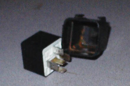
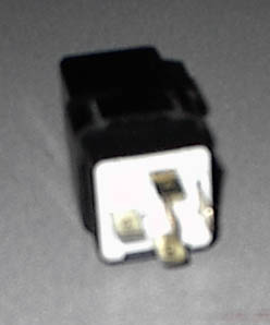
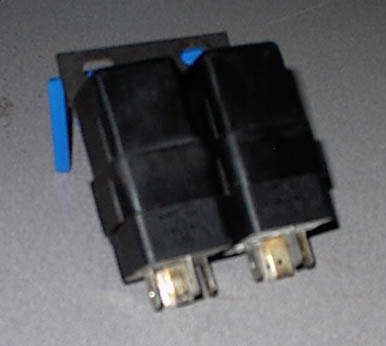
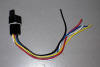
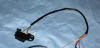
This is the
hard part, you have to cut the relays cables one by one and
use new connectors to attach them to the relay. Be careful
to not miss place the wires or it wont work. In the RS
electrical center you can see in the relays connectors that
are numbered, 1 to 5, just plug them in the same way. Go and
get the Fiero relays and take the "inner coil stuff" out, we
going to reuse the outer case to hold our new custom made
relays. Then place the 3.4 DOHC relays inside the case of
the older Fiero relays, look the pics. You can place them in
the engine bay using this method.
|
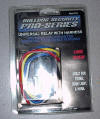
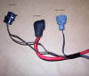
Or you can
place them inside of the car, where the Fiero ECM should
be. There is a kit (relay and connector) in Western Auto
for $5.99. BTW, don't use the relays that comes in the
package, use the 3.4 DOHC instead. You can use the
connector plug to replace the RS electrical center
connectors, maybe the use of some wires as extensions
will be required. Do one by one and verify its location,
if you miss connects the wires the fuel or a/c may not
work. |
 |
 |
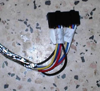
ALDL Connector
|
DOHC |
Description |
Fiero |
|
Position |
Wire Color |
|
Position |
Wire Color |
|
J1 |
White/Black |
ALDL
Enable diagnostic |
B |
White/Black |
|
J4 |
Orange |
ALDL ECM
serial data I/O |
E |
Orange |
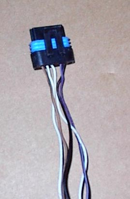
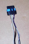
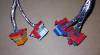
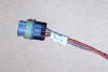
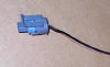
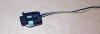
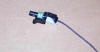
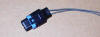
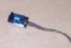
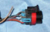
Connectors
|
3.4 DOHC Harness Plugs |
|
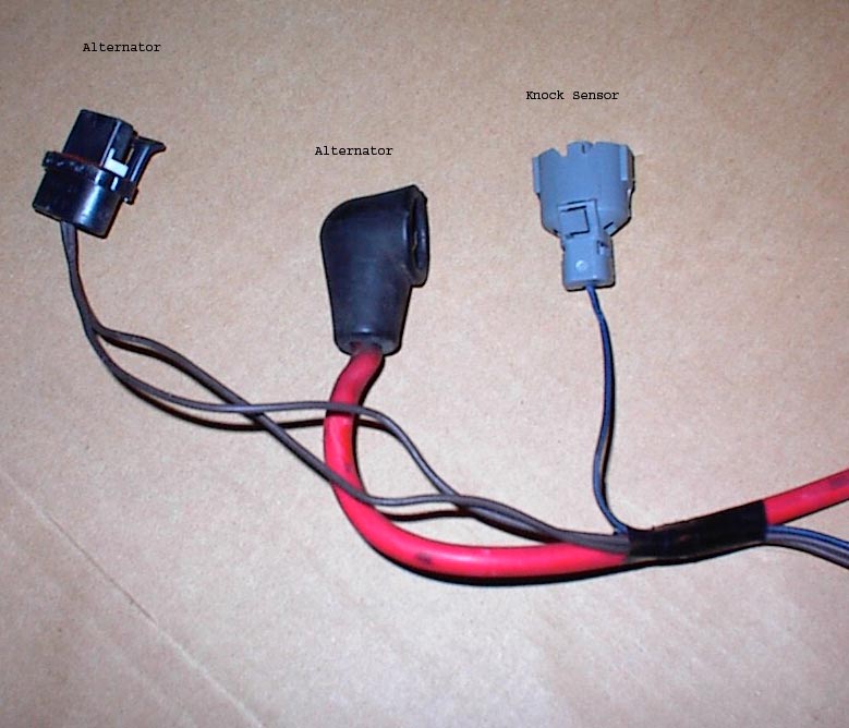
Alternator
and Knock Sensor Connector
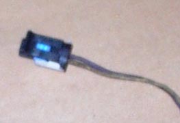
 |
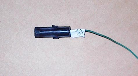
Coolant
Temp Connector
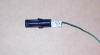 |
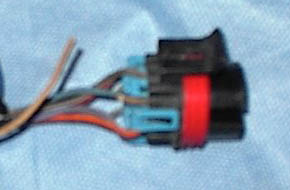
DIS
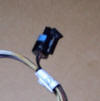 |
DIS
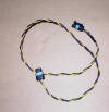 |
DIS
 |
|
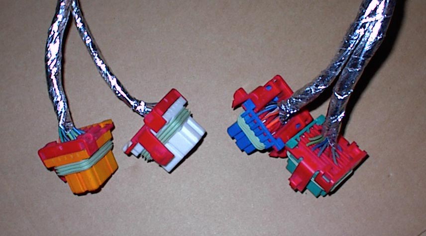
ECM
Connectors
 |
Fuel Pump
Oil pressure switch
 |
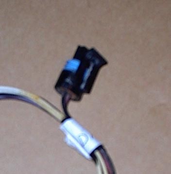
IAT Sensor
Connector
 |
Low
Coolant Temp Indicator
 |
O2 Sensor
Connector
 |
|
Power
Steering Pressure Switch
 |
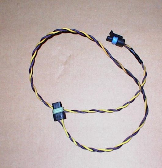
VSS
Connector
 |
Auto
tranny connector
 |
|
|
|