- I guess, the
first question anyone would ask me is "Why?". Why build it
yourself when you can get them so inexpensively? Let's face
it, Summit Racing offers it for less than $30 complete! Cool
factor and sense of accomplishment are the first things I
respond, plus it gives you a range of mounting options you
don't have in a pre-canned package, like how about a stealth
mount in the dash or gauges. In addition, these have an
adjustment feature that lets you "tune" the gauge for more
detail that the big makers don't give you and an adjustable
brightness control. In any case, these can be done for around
$10-$15 easily and are every bit as accurate as many others
that you pay bigger bucks for.
-
- Parts
List
-
- DOT/Bar
Display Driver - National Semiconductor
LM3914N
Voltage Regulator -
National Semiconductor
LM340MP-5.0
or Radio Shack
#276-1770
- 10
Segment LED BarGraph - Radio Shack
#276-081
-
Resistors (2.3k
and
3.3k)
- Mini
Circuit Board - Radio Shack
#276-148
Misc Wires as needed
- 18 Pin
socket - Radio Shack
#900-5741
- 20 Pin
socket - Radio Shack
#900-5742
-
Optional Parts:
The Run
Down
My first
suggestion is to always use chip sockets when soldering to
chips. This way the chip itself doesn't take any heat causing
potential failure and undue headaches in trying to troubleshoot.
If you solder a bunch of wires from the chip socket to the LED
socket you can have some placement flexibility for the LED
display, like in the dashboard. Be aware that LED's have a
Positive side and Negative side. There's a flat spot in the
corner of the BarGraph 'chip' to indicate Pin 1.
There are
many different ways to make this a clean, well executed project,
but as always, the end result is from your own efforts. Such
niceties as terminating the wires with connectors and what not.
You can also use floppy drive ribbon cables to connect all the
circuits together, which will make it easy and neat to mount the
LED graph separately.
Most
people want the wide band of the O2 measuring from 0-1v. But
some might want a Finer Resolution. Where it'll measure from
0.4-1v. This would mean that the 1st LED will be ~0.4v and the
10th LED will be 1v. Engines equipped with a turbo, blowers, or
Nitrous, might want a finer resolution as the Air / Fuel ratio
is especially critical for those motors. In a Naturally
Aspirated engine, the finer resolution might not be necessary as
the proper mixture (14.7:1) is at about 0.5v from the O2 sensor.
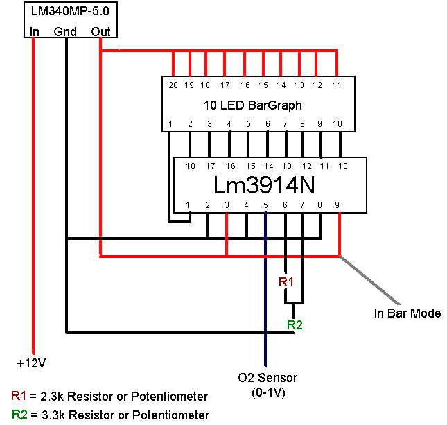
Resistor
R1 is what determines the resolution for the LED display.
Resistor R2 is what determines the relative brightness of the
LED. You can stick potentiometers in place of these resistors in
order to fine tune the bar graph resolution and display
brightness and is highly encouraged for flexibility. If you
decide to use the Potentiometer (POT) you need to get an Ohm
meter and measure the range at which resistance ranges from 2.3k
to 3.3k . As it is adjustable, you can adjust it on the fly.
In order
to run the display at the finest resolution possible, take out
R1 and run it straight with no resistor in there. It should be
that simple. During experimentation I had the resolution up to
0.7v as the 1st led, but I can't figure what was done to get
this measurement. Feel free to play around with it and let us
know if you find something that works better.
Currently
it is setup as BAR mode. If you prefer DOT mode, disconnect pins
3 and 9. DOT mode is when one LED will light up at a time, while
BAR mode all lights will light up, building to the final value.
Installation is as straight forward as it could be. Hook
up the power to an to a switched power source, and connect up
the ground to a solid ground. Connect up the Signal Wire to your
O2 sensor. Remember that your ECU will need signal too for fuel
adjustment. Note: the voltages from the O2 sensor are
very low, so take extra care in taping the signal wire and make
a high quality connection. It's highly suggested to solder the
connection properly and use heat shrink tubing to seal it.
The table
below represents what the LEDs indicate on a non modified gauge
in wide resolution mode. You can use a Volt/Ohm meter on the
signal wire to take a reading directly from the O2 sensor to
recalibrate your lights in the fine resolution mode. These
should be pretty close, but don't hold me to these values.
LED 10 -
0.97V - 12.1:1 - Very Rich -
Forced induction and nitrous.
(All LEDs on)
LED 9 -
0.88V - 12.7:1
LED 8 -
0.78V - 13.2:1
LED 7 -
0.69V - 13.8:1
LED 6 -
0.59V - 14.4:1
LED 5 -
0.49V - 14.9:1 - Stoich- This is where NA motors should be at
LED 4 -
0.39V - 15.4:1
LED 3 -
0.30V - 16.0:1
LED 2 -
0.20V - 16.5:1
LED 1 - 0.10V -
17.1:1 - Lean (The only LED on)
Author:
85frankenstein |